-
Studios
-
Support
-
Contact us
-
Products
Studios
GUL Screening uses guided wave technology as a solution to the rapid detection of corrosion, erosion and other damages in steel pipes and rail. This is an advanced non-destructive testing (NDT) method used for pipe and rail inspection.
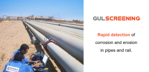
It is used to rapidly, accurately and reliably:
(1) Detect and locate the axial location of defects.
(2) Locate circumferential positions of defects.
(3) Estimate defect severity by cross-sectional area change
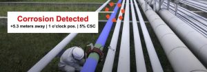
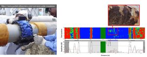
Originally designed for detection of corrosion under insulation (CUI), GUL Screening’s application has expanded into many other areas including detection and location of corrosion under pipe supports (CUPS), pitting corrosion and many more; please see the Case Studies section.
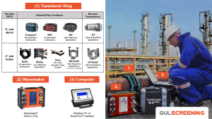
The Wavemaker® is the brand name of the guided wave system that GUL Screening utilises. The system comprises of 3 primary components, namely the transducer ring, Wavemaker® instrument and laptop computer.
Long range ultrasonic testing (LRUT) was a term coined in the early 1990s to describe guided wave testing of pipes. However, the term “long-range” in LRUT is misleading because the inspection range can vary from 2 m to 150 m (6 to 492 feet ) per sensor direction depending on pipe conditions. GUL Screening is the latest term used to describe guided wave testing because it emphasises the “Screening” or detection component of this NDT method.
GUL Screening offer solutions to pipe with diameters from 0.75 inch (19.05 mm) and above. The applicable pipe wall thicknesses range from 3 mm to 40 mm (1/8 to 1.57 inch). We have a range of transducer ring types and sizes to meet your inspection requirements. Please contact us separately for custom sizes.
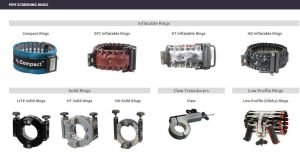
GUL Screening can be applied on both Seamless and Seamed (spiral or longitudinal welded) pipes, made from:
Here is a non-exhaustive list of pipes that GUL Screening is applicable to:
GUL Screening is currently not possible for pipes made from:
In ultrasound, there are two types of waves, namely the Guided Waves and Bulk Waves.The existence of these waves depends on the material geometry (shape, thickness) and the inspection frequency or wavelength. Therefore, at relatively low frequencies (~25 kHz), Guided Waves can exist in pipes (and other geometries) because the wavelength is relatively much larger than the wall thickness of the pipe. For example, guided wave signals at 25 kHz typically have a wavelength of 130 mm and pipe wall thicknesses are typically within the range of 3 to 40 mm (1/8 to 1.57 inch).
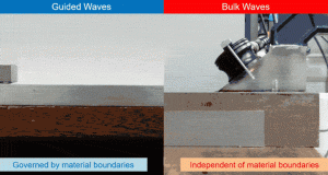
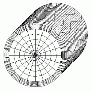
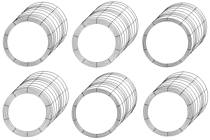
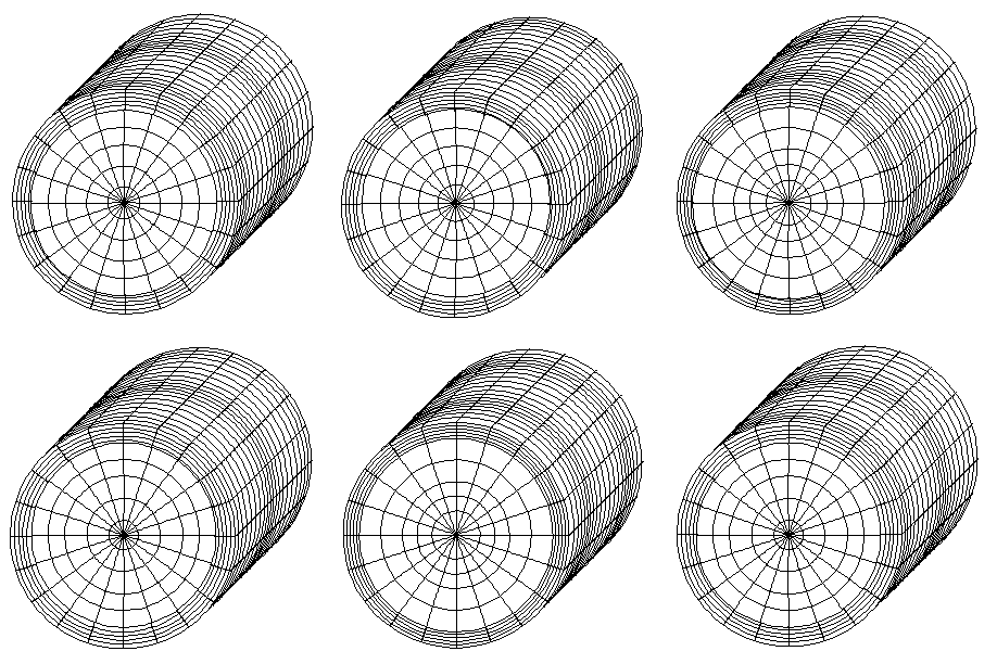
Different types or modes of guided waves can exist for different structures (e.g. pipes, plates, rails) since guided waves are dependent on the material geometry. In the context of pipe inspection, the two most common types of pipe guided waves modes for guided wave testing are the Torsional T(0,1) and Longitudinal L(0,2) modes. The fundamental Torsional and Longitudinal waves are analogous to the Shear and Compressional waves in Ultrasonic Thickness (UT) testing respectively.
Torsional T(0,1) mode
Longitudinal L(0,2) mode
The Guided Waves can propagate along the pipe at velocities that can be determined from Dispersion Curves. The Dispersion curve is a graph of phase or group velocity against the signal frequency (or the product of frequency and thickness). This plot shows how the velocities of the guided wave vary according to the mode and frequency.
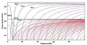
The plot above is the group velocity dispersion curves for an 8″ schedule 40 steel pipe generated using DISPERSE. The fundamental longitudinal L(0,1), torsional T(0,1) and flexural F(1,2), F(1,3) and F(2,3) wave modes have been labelled.
GUL Screening uses the fundamental torsional wave, known as T(0,1), for three main reasons.
Firstly, the T(0,1) guided wave mode has a constant speed that does not depend on frequency (i.e. non-dispersive). This allows us to accurately measure the exact locations of defects by using time-of-arrival calculations. Secondly, only a single fundamental mode T(0,1) exists at low frequencies which improves the signal-to-noise ratio (SNR) of the data by decreasing noise levels due to other modes.
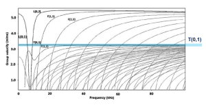
Thirdly, the T(0,1) mode is not affected by liquid contents in the pipe. These 3 advantages help to reduce inspection complexity, give higher signal-to-noise ratio (SNR) and a higher range of inspection applications.

Conversely, we do not use the longitudinal waves for inspection because the wave speed varies with frequencies (dispersive), there are more than 1 fundamental modes and they are affected by liquid contents in the pipe. Therefore, using the Longitudinal wave can introduce a bigger error due to varying speeds, poorer SNR due to an additional mode and inability to inspect pipes with liquid contents. The figure below shows a comparison in inspection results between the T(0,1) and L(0,2) guided wave modes.
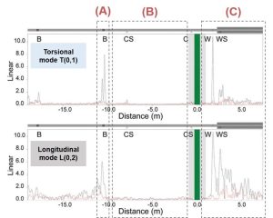
(A) T(0,1) has a lower coherent noise at the bend which increases the probability of detection (POD) of erosion; L(0,2) shows high coherent noise at the bend.
(B) T(0,1) has a better signal-to-noise ratio (SNR) which increases the POD of smaller corrosion patches; L(0,2) has poorer SNR.
(C) T(0,1) gives a better SNR after the welded support for a higher POD of corrosion patches after the welded support; L(0,2) has significantly poorer SNR which reduces inspection range and lower the POD of corrosion.
GUL screening is capable of using L( 0,2 ) using 4 row solid rings, however there are virtually no applications where this gives better results than using the torsional mode.
The torsional T(0,1) guided wave is generated within the pipe, via a ring of transducers. The guided wave will travel away in both direction from transducer ring at a speed of approximately 3,250 m/s (10,662 ft/s). The waves will be reflected from both pipe features (e.g. welds, supports, flanges) and defects (e.g. corrosion, erosion, mechanical damage), causing the signal to travel back towards the transducer ring. GUL Screening works by collecting and analysing the properties of these reflected waves (e.g. time of arrival, torsional and flexural contents).

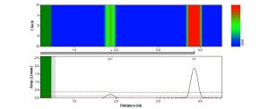

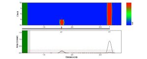
The A-scan is a plot that shows the reflected guided wave signals against the pipe axial distance. The black and red signals are the torsional and flexural components of the reflected signal. The x-axis represents the relative distance of the signal from the transducer location. In other words x = 0 m is the transducer ring location and the positive and negative distances represents the forward and backwards direction from the transducer ring.

The DAC curves provide a quantitative link (or calibration curve) between the signal amplitude and cross-sectional area change (CSC) within the pipe. so that we can ultimately quantify the extent of the damages in terms of pipe CSC. An accurate DAC curve is required to call the severity of defects in pipes
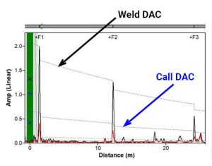
The figure above shows an A-scan with the Weld and Call DACs labelled. In most inspections, the Weld DAC is established by using either weld size parameters or via the Absolute Calibration method. This results in a calibrated Call DAC, which can be used to estimate defect severity and determine end of inspection test range.
The Call DAC is the threshold level that is used to determine the defect severity if found. Typically, it is set at 6% CSC, but this can vary according to the sensitivity requirement of the inspection.
Absolute Calibration is GUL’s patented method of calibrating the DAC curves. Put simply, this method uses reverberation signals from pipe features, such as welds or flanges, to rapidly and accurately calibrate the DAC curves.
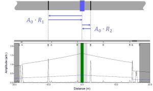
What is Unrolled Pipe Display in GUL Screening?
The Unrolled Pipe Display is a colour plot that shows the guided wave reflection amplitude as a function of axial distance and circumferential position. This plot is generated by using a proprietary algorithm that enables total focusing of the guided wave signals at all locations (within the valid inspection range), analogous to Total Focusing Method in phased array UT.
Using post processing to produce the unrolled display avoids the need to collect additional data making the inspection faster.

Identifying and eliminating pipe features is typically performed before an inspector sets out to detect defects in GUL Screening. This can be done by visual inspection on site, referring to engineering drawings and studying and characterising the reflection signal; e.g. weld signals are easily distinguishable by their high torsional component and uniform amplitude around the cross-section.
The Level 1 and 2 GUL Training (GULT) courses are designed to equip inspectors with the skills and knowledge to confidently and competently perform this task.
In general, the reliable detection sensitivity is 5% cross-sectional area change (CSC). Smaller defects, as small as 1% CSC, can be detected but is subject to the signal-to-noise ratio (SNR) level of the test. Essentially, the SNR level of the data determines the detection sensitivity.
The SNR level is mainly affected by the existing condition of the pipe. For example, a pipe in good condition will yield a higher SNR than a pipe that has severe general corrosion along its entire length.
The accuracy of defect location is ±100 mm (approx. 4 inches). By measuring the distance from the closest visible feature, defects can be located more precisely.
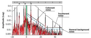
There are 2 types of noise considered in GUL Screening, namely coherent and incoherent noise. Coherent noise is not random and can be attributed to the pipe condition, corrosion, scales and other features that causes unwanted guided wave scattering. Incoherent noise is random (i.e. can be reduced by signal averaging) and is attributed to background and electrical noise.
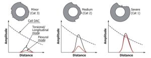
After identifying a defect in the A-scan, the defects can be classified further as Minor, Intermediate and Severe. The classification is determined based on the cross-sectinonal area change (CSC), the circumferential extent of the signal and their relationships with the call DAC level.
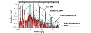
The inspection range can either be determined by the intersection of the Call and Detection Threshold (DT) or by limited by certain pipe features such as flanges or elbows. The DT is typically defined as 6 dB above the noise level.
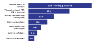
In ideal circumstances, the test range can be more than 200 meters (656 feet) in each direction. However, this may not always be the case as the inspection range can be limited by attenuation due to pipeline properties (coatings, surrounding environment and existing pipe metal condition) or features such as bends or flanges.
The figure below provides a guide to the typical and average inspection range for GUL Screening.
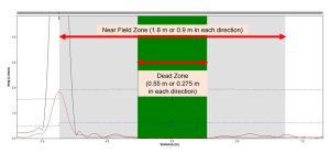
The dead zone is indicated by the green area in the A-scan. Data is not available in this area because the transducers are still transmitting the signal and not receiving any (pulse-echo configuration).
The near field zone is the gray area next to the dead zone in the A-scan. Data is available in this region, but should not be used for defect detection because the system is transitioning from a transmit to a receive mode, which affects the received amplitudes.
The size of the dead zone and near field zone are a affected by the frequency of the guided wave signal (higher frequencies = smaller zones). It can be estimated that the length of dead zone and near-field zone are 0.275 m (1 foot) and 0.9 m (3 feet) per sensor direction respectively.
GUL Screening can be used for detection of:
GUL Screening can be used to inspect:
| Pipe Feature | Can a 5% CSC defect be reliably detected on/at this feature? | Can we use data past this feature for GW inspection? | GW Inspection Comments |
|---|---|---|---|
| Girth Welds | Yes – observe for increased flexural content. | Yes | Important features for DAC calibration. |
| Spiral Welds | Yes, if welds are grounded and flush with pipe surface. | Yes | Pipe with this feature can be inspected but be wary of coherent noise level. |
| Simple Support | Yes – observe for increased flexural content. | Yes | Use unrolled pipe display to determine if reflection is at 6 o’clock. Reflection values will depend on pipe stress at the support location. |
| Drain/Vent | Yes – observe for increased flexural content. | Yes | Coherent noise caused by trailing echoes from the feature. Higher frequencies may reduce this effect. |
| Clamped Supports | Yes – for relatively loose clamps. | Yes – for relatively loose clamps. | It may be necessary to loosen clamps during GW inspection for best performance. |
| Welded Supports | Yes, if coherent noise reduced with higher inspection frequencies + good SNR. | Yes | Use higher inspection frequency to reduce coherent noise from this feature. |
| Concrete Anchor Supports | Yes | Yes | Use higher inspection frequency to reduce coherent noise from this feature. |
| Bushings | No | No | Guided waves do not propagate past this feature due to screw-type fitting. |
| Pipe Elbows | Yes | No – For short radius elbows and relatively small diameter pipes. | For short radius elbows (< 3D bends) and relatively small diameter pipes (< NPS 12), the Inspection data becomes less sensitive and reliable after the second bend weld. |
| Pipe Caps | No | No | Guided waves do not propagate past this feature due to 100% discontinuity. |
| Crosses | Depends on defect location and properties of the branch. Generally no – if same diameter. | Depends on defect location and properties of the branch. Generally no – if same diameter. | Reflection/noise would depend on ratio of opening diameters. Guided wave would typically propagate past this feature and continue inspection in the direction of the pipe where the transducer ring is attached. The branch distorts the 2nd weld, making it non-symmetric. |
| Flanges | No | No | Guided waves do not propagate past this feature due to rubber seal and 100% discontinuity. |
| Concentric Reducers | No | Yes – but not recommended. | Guided waves can propagate past this feature, but generally inspection past this should be treated with caution. Any indication should be followed up by additional guided wave test locations on the smaller diameter pipe after the reducer. |
| Nipples | No | No | Guided waves do not propagate past this feature. |
| Fitted Branch (Tee) | Depends on defect location and properties of the branch. Generally no – if same diameter. | Depends on defect location and properties of the branch. Generally no – if same diameter. | Reflection/noise would depend on ratio of opening diameters. Guided wave would typically propagate past this feature and continue inspection in the direction of the pipe where the transducer ring is attached. The branch distorts the 2nd weld, making it non-symmetric. |
| Unions | No | No | Guided waves do not propagate past this feature due to screw-type fitting. |
| Valves | No | No | Guided waves do not propagate past this feature. |
| Link Seal | Yes | Yes | Little-to-moderate reflection at the interfaces; potentially some attenuation within this feature. |
Transducer rings: From -40°C to +350°C (-40 to 662°F). The operating temperature varies across different transducer ring types.
| Transducer ring type
|
Pipe operating temperature range
|
|---|---|
| Compact, EFC, HD Inflatable, HD Solid, Solid, | -40°C to +150°C |
| HT Inflatable, HT Solid, HT-HD Solid | -40°C to +350°C |
LEMO connectors: -40°C to +482°C (-67 to 662°F); according to equipment/component
LEMO cables: -40°C to 482°C (-76 to 662°F); according to equipment/compone
The GUL Screening is applicable to pipes with coatings or paint thicknesses of up to 1 mm (3/64 inch).
Yes. Please see links below:
GUL Case Studies
Using the default data collection procedures, data collection using the Wavemaker G4mini typically takes 2 minutes.
GUL Screening is currently not applicable to finned tubes or pipes due to the relatively large coherent noise generated from the reflections of the fins.
Reducers can often be inspected through as it depends on the relative size change. For example NPS14:NPS12 (DN350 to DN300) has little effect whereas NPS4:NPS2 (DN100 to DN50) would result in a much bigger signal loss.
Bends are similar – there is always some loss of signal, the tighter the bend the greater the loss. Analysis of the data allows the level of loss to be quantified so that the level of sensitivity obtained around the bend is known.
GUL Screening generates an Unrolled Pipe Display, which appears very similar to a conventional corrosion map. However, it shows cross-sectional area change (CSC) and does not directly map wall thickness. Nevertheless, it will locate areas of wall loss and we are able to estimate remaining wall for these areas.
Yes. To estimate the inspection range, we would need to know the thickness of the concrete lining and the pipe wall thickness, as well as the information on the condition of the concrete bond to the pipe, or if bonded at all.
GUL Screening is not designed for measuring stress in pipes.
GUL Screening require a specific transducer ring size for a specified nominal pipe size; a single ring size can tolerate small differences in the equipment’s intended nominal pipe diameter. For example, to inspect an NPS 8 pipe, you would need a NPS 8 Compact ring. The photo below shows a range of Compact ring with different sizes.
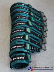
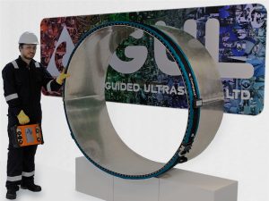
Two transducer rings can also be combined to form one larger ring. For example, a 30″-Compact and a 26″-Compact can be combined to inspect NPS 60 (DN 1500) pipes.
| Compact Ring Combine Size Chart | |||||||||||||||||||
|---|---|---|---|---|---|---|---|---|---|---|---|---|---|---|---|---|---|---|---|
| These combinations are not recommended. |
Long arm required on at least one ring. |
||||||||||||||||||
| Ring
Size |
8 | 10 | 12 | 14 | 16 | 18 | 20 | 22 | 24 | 26 | 28 | 30 | 32 | 34 | 36 | 38 | 40 | 42 | |
| 8 | 20 | 22 | 24 | ||||||||||||||||
| 10 | 22 | 24 | 26 | 28 | |||||||||||||||
| 12 | 24 | 26 | 28 | 30 | 32 | ||||||||||||||
| 14 | 28 | 30 | 32 | 34 | 36 | ||||||||||||||
| 16 | 32 | 34 | 36 | 38 | 40 | ||||||||||||||
| 18 | 36 | 38 | 40 | 42 | 44 | ||||||||||||||
| 20 | 40 | 42 | 44 | 46 | 48 | ||||||||||||||
| 22 | 44 | 46 | 48 | 50 | 52 | ||||||||||||||
| 24 | 48 | 50 | 52 | 54 | 56 | ||||||||||||||
| 26 | 52 | 54 | 56 | 58 | 60 | ||||||||||||||
| 28 | 56 | 58 | 60 | 62 | 64 | ||||||||||||||
| 30 | 60 | 62 | 64 | 66 | 68 | ||||||||||||||
| 32 | 64 | 66 | 68 | 70 | 72 | ||||||||||||||
| 34 | 68 | 70 | 72 | 74 | 76 | ||||||||||||||
| 36 | 72 | 74 | 76 | 78 | 80 | ||||||||||||||
| 38 | 76 | 78 | 80 | 82 | 84 | ||||||||||||||
| 40 | 80 | 82 | 84 | 86 | |||||||||||||||
| 42 | 84 | 86 | 88 | ||||||||||||||||
| EFC, HT, HD Ring Combine Size Chart | |||||||||||||||||||
|---|---|---|---|---|---|---|---|---|---|---|---|---|---|---|---|---|---|---|---|
| These combinations are not recommended. |
Long arm required on at least one ring. |
||||||||||||||||||
| Ring
Size |
8 | 10 | 12 | 14 | 16 | 18 | 20 | 24 | 28 | 30 | 32 | 36 | 40 | 42 | |||||
| 8 | 21 | 23 | 25 | ||||||||||||||||
| 10 | 23 | 25 | 27 | 28 | |||||||||||||||
| 12 | 27 | 29 | 30 | 32 | |||||||||||||||
| 14 | 28 | 30 | 32 | 34 | 36 | ||||||||||||||
| 16 | 32 | 34 | 36 | 38 | 40 | ||||||||||||||
| 18 | 36 | 38 | 40 | 42 | |||||||||||||||
| 20 | 40 | 42 | 44 | 48 | |||||||||||||||
| 24 | 48 | 52 | 56 | 58 | |||||||||||||||
| 28 | 56 | 60 | 62 | 64 | |||||||||||||||
| 30 | 58 | 62 | 64 | 66 | 70 | ||||||||||||||
| 32 | 64 | 66 | 68 | 72 | |||||||||||||||
| 36 | 70 | 72 | 76 | 80 | 82 | ||||||||||||||
| 40 | 80 | 84 | 86 | ||||||||||||||||
| 42 | 82 | 86 | 88 | ||||||||||||||||
A long arm is an accessory for the inflatable transducer rings. It is required when combining rings to inspect larger diameter pipes in order to ensure the combined ring can successfully close and be secured on to the pipe. In some cases, the long arm can also be used to allow one ring to inspect pipe sizes slightly larger than the designed inspection size. For example, a 28″ EFC ring can be used to inspect an NPS 30 (DN 750) pipe.

For more info, you can refer to our spare parts for inflatable rings webpage.
| Transducer ring type | Radia Clearance |
|---|---|
| Compact
|
38 mm |
| Inflatable EFC, HD and HT
|
63 mm |
| Solid ring
|
76 mm |
| HT Solid, HD Solid and Claw
|
50 mm |
| Slinky
|
25 mm |
Calibration is recommended for the Wavemaker G4mini (or older generation system) and its calibration certificate is valid for 3 years. The transduction system must be shipped back to GUL annually for calibration.
Most of our equipment is supplied with a one year warranty. It is possible to purchase an extended warranty for some sorts of equipment (for example the electronics). Please note that the warranty only allows for normal wear and tear of the equipment; it does not cover misuse of the equipment such as large drops or immersion in water.
Typically, we offer cable lengths of up to 25 meters, however cable lengths can be as long as 100 meters.
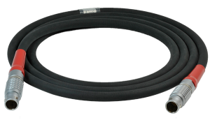
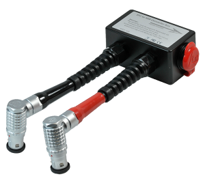
In order to inspect large diameter pipes, two rings can be joined together using the 16 to 8 Channel Converter Box. However, the setup is only for testing a single pipe at a time (Connecting rings on multiple pipes at the same time is really only relevant for connecting multiple gPIMS to an autonomous data collector).
For technical enquiries, please contact us at support@guided-ultrasonics.com.
For more information, please see GUL Software Updates webpage.
The TRUNK is GUL’s cloud platform that provides data storage and analysis services for our customers.
No, remote upgrading is not possible. In order to upgrade the firmware of a G4mini Base to a Full, the equipment would need to be returned to GUL(UK).
The GUL Screening results can be exported out to a variety of formats including Microsoft Word, Excel or PDF; export into other formats can be done upon request and discussion.
For technical enquiries, please contact us at support@guided-ultrasonics.com.
Typically, a Level 2 GULT qualified and certified operator is required to perform GUL Screening; Level 1 operators can assist a Level 2 operator(s). For more information on training, please see GUL Training webpage.

Step (1) : Download the Repair Request Form.
Step (2) : Fill up the required details in the form.
Step (3) : Email it to repair@guided-ultrasonics.com.
Step (4) : A GUL member will contact you once they have received and processed your repair request form.
After investigation of the equipment, we will normally provide a quotation for the repair and ask for a PO (and in some cases payment) before proceeding with the repair. We seek to repair all items within two weeks of receiving them in our office.
However, this may be extended if we do not have all of the required parts on hand, there are a lot of items to be repaired, it is a holiday week in the UK, or there are delays in getting approval for the repair.
Yes, GUL offer consultancy services on reviewing GUL Screening data. For a price quotation, please email your enquiry to info@guided-ultrasonics.com.
For more information, please see GUL Repair and Servicing webpage.
Check out the GUL Screening webpage.

Please send us a message on our Contact Us page. We will be happy to help.
For the G4mini battery MSDS, please see Battery MSDS.
For the G4mini CE DoC, please see CE DoC.